
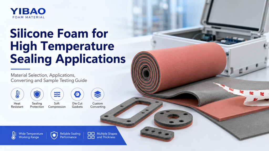
For tool cases, test instruments, electronics kits, service equipment, and presentation boxes, custom foam inserts help control product position, reduce movement, organize accessories, and protect fragile areas during repeated handling. A strong insert design begins with the case goal, product shape, material direction, cutting method, and sample fitting plan.
Start With the Tool Case or Equipment Packaging Goal
First, a foam insert should be planned around the real purpose of the case. A field service kit needs fast tool access and clear return positions. A precision instrument case needs controlled movement, careful clearance, and soft support around sensitive areas. A demonstration case needs a clean opening view and a complete set layout.
Therefore, the first design question should not be only about foam material. A better question is what the insert must control. In tool cases and equipment packaging, that usually includes movement, surface contact, stacking pressure, accessory separation, removal comfort, and repeat packing accuracy.
In addition, the insert should match the case structure. A plastic hard case, aluminum case, cardboard equipment box, and molded carrying case all have different inner space limits. Hinges, ribs, lid foam, corner radius, and latch areas can affect the final insert shape.
A design that looks neat on a flat drawing can still fail if the case closes poorly or if a tool is difficult to remove. For this reason, insert planning should connect product geometry, material behavior, case space, and the expected handling route from the beginning.

Converted foam structures are suitable when a case requires shaped cavities, clean edges, notches, layered support, adhesive backing, or repeatable part positioning.
View Converting FoamBest-fit project profiles
A fitted insert is especially useful when a product set must remain organized after storage, transport, inspection, or repeated use. It can also support production teams that need a clear packing standard before shipment.
- Maintenance tool cases with wrenches, sockets, bits, screwdrivers, gauges, and hand tools.
- Portable instrument cases for meters, sensors, testing devices, and calibration equipment.
- Electronic equipment packaging with a main device, cable set, charger, adapter, and small modules.
- Sample presentation kits where clean spacing and missing-part visibility matter.
- Reusable transport cases for industrial spare parts, service kits, and inspection tools.
Measure Product Shape, Weight, Fragile Areas, and Movement Risk
Next, the product itself should guide the insert layout. Outer length, width, and height are only the starting point. Real design also depends on weight, center of gravity, raised features, fragile surfaces, and the direction in which the case moves during handling.
For example, a measuring device may include a screen, connector, dial, lens, button, or coated surface. These areas should not become the main pressure points. Instead, the cavity should support stronger housing zones and leave enough clearance around delicate details.
Meanwhile, movement risk should be reviewed early. A product may sit still on a table, yet slide inside a case during vehicle transport, warehouse transfer, air shipment, or repeated opening. For transport-related packaging projects, ASTM packaging standards include topics related to shock, vibration, impact, and shipping container performance.
Therefore, foam insert planning should look beyond a single static position. It should consider vertical pressure, side movement, rotation, accessory contact, and lid compression at the same time.
Shape details
Record outline, height changes, feet, handles, ports, clips, raised labels, and irregular edges. These details affect cavity clearance and notch placement.
Weight and support
Check where the product can safely carry pressure. Heavy items may need wider support zones, deeper pockets, or firmer base layers.
Fragile areas
Mark screens, lenses, coated surfaces, connectors, switches, dials, and cable ports. These zones often need clearance instead of tight holding.
Movement direction
Review flat storage, upright carrying, side tilt, stacking, and repeated opening. The insert should limit movement from more than one direction.
Support the structure, not the weakest feature
A common design mistake is copying the outer outline too closely. Although the shape may look accurate, it can press on the wrong part of the product. This is especially risky for screens, ports, rubber buttons, optical components, and polished surfaces.
A safer design begins with support points. The foam should contact strong product areas first. After that, clearance should be added around details that should not carry pressure. This method makes the insert more practical in real use.
Choose EVA Foam, PE Foam, or Other Materials by Function
After product risk and case purpose are clear, material selection becomes easier. EVA and PE foam are common directions for tool case inserts and equipment packaging, yet they serve different needs. EVA often supports clean layouts and firm holding. PE often supports practical cushioning and lightweight blocking.
However, material names alone do not determine performance. Thickness, density, hardness, surface feel, cavity depth, layer structure, and cutting process all influence the final fit. A sample should confirm the final direction before repeat production.
In many projects, a mixed structure also makes sense. For example, an EVA top layer can define a clean cavity layout, while a PE base layer can support cushioning under heavier equipment. The best structure should follow the product and case, not a fixed template.
EVA foam for clean tool case layouts
EVA foam is often selected when the insert needs a firm feel, clean cutouts, stable walls, and a neat opening view. It can support tool kits, sample cases, electronics boxes, hardware sets, and reusable service cases.
In addition, EVA works well for layered layouts. A dark top layer with a contrast base layer can show missing tools quickly. This is useful when a complete kit check matters before the case returns to storage or moves to the next task.
At the same time, EVA should still match the product weight and cavity depth. A narrow heavy tool may create pressure in one area if the support surface is too small. Therefore, tool weight and contact area should be reviewed together.
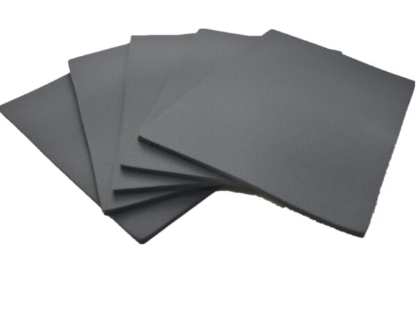
EVA foam can support firm cavity walls, clean tool positioning, layered contrast, and presentation-focused case layouts.
Explore EVA FoamPE foam for larger equipment and practical cushioning
PE foam is often considered when larger equipment needs lightweight cushioning, blocking, spacing, or shock reduction. It can support instrument packaging, case liners, equipment pads, transport blocks, and inner packaging structures.
Meanwhile, PE can be practical when the insert must control movement without a premium display requirement. It is useful for industrial equipment packaging where stable support, closed-cell cushioning, and production efficiency all matter.
Still, cavity geometry remains important. A strong foam material cannot solve a poor layout if the product has too much room to move. Therefore, material choice and cavity design should be reviewed as one system.
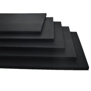
PE foam is useful for cushioning, case lining, spacing, blocking, and larger equipment packaging support.
View PE FoamOther foam directions when special conditions matter
Some equipment cases need more than basic cushioning. A case used near heat, oil, outdoor exposure, compression cycling, sealing contact, or electrical parts may require rubber foam, silicone foam, EPDM foam, CR foam, or another functional foam direction.
However, special foam should match a real working condition. If the insert mainly needs clean tool positioning, EVA may already be enough. If the package mainly needs larger-area cushioning, PE may be more practical. The correct direction should come from the application, not from material names alone.
Practical Foam Insert Selection Table
The following table gives a practical starting point for tool case and equipment packaging projects. It should not replace physical sample fitting, but it can narrow the first material and process direction.
| Project situation | Suggested direction | Useful structure | Design focus |
|---|---|---|---|
| Hand tool case | EVA foam | Single layer or contrast layer | Clear tool positions, notches, missing-tool visibility |
| Measuring instrument case | EVA or PE foam | Deep cavity plus lid support | Avoid pressure on displays, ports, and dials |
| Large equipment packaging | PE foam | Thick pads, blocks, or layered support | Weight distribution, bottom support, side movement |
| Sample presentation kit | EVA foam | Color contrast, clean cavities | Visual order, consistent spacing, easy inspection |
| Accessory and cable set | EVA or PE foam | Pockets, channels, shallow trays | Separate hard parts from sensitive surfaces |
| Pilot or low-volume equipment case | CNC cut foam | Routed cavities and adjustable sample design | Fast revision before the layout is locked |
Plan Cavities, Finger Notches, Layering, Color Contrast, and Tolerance
Once material direction is clear, cavity planning becomes the main design task. A cavity is the shaped space that holds the product. It should control movement without making removal difficult or causing harmful pressure.
Therefore, cavity design should balance fit, access, wall strength, clearance, and production tolerance. A tight insert may look secure in a photo, but repeated handling can create scratches, edge wear, or slow packing. A loose insert may feel easy to use, yet it may allow vibration and impact inside the case.
The best cavity design usually feels controlled, not forced. It allows the product to sit in the same position every time while leaving safe access for fingers and enough clearance around sensitive details.
Cavity depth
Cavity depth affects stability and access. A shallow cavity can make a tool easy to remove, but it may not control side movement. A deep cavity can hold equipment more securely, but it should include enough space for safe lifting.
For heavy tools, deeper support can help reduce rotation inside the case. For sensitive equipment, depth should also consider lid pressure. If a top foam pad presses the product, that contact should happen only on safe areas.
Finger notches
Finger notches improve daily handling. A small half-moon notch may work for light parts, while larger equipment may need two-sided access. In deeper cavities, a stepped edge can help lift the item without twisting it.
However, notches should not weaken the foam wall. If two pockets sit too close, the narrow bridge between them can tear or bend. For this reason, spacing should be reviewed together with notch shape.
Layered insert structures
Layering gives the insert more design control. A top layer can define the visible outline. A middle layer can create depth. A base layer can add cushioning, color contrast, or support under the product.
For tool control, a contrast base layer can show missing tools at a glance. For equipment packaging, layered construction can support a deep cavity without forcing one thick sheet to carry every detail.
Tolerance and clearance
Tolerance is the planned difference between product size and cavity size. It should account for foam compression, cutting variation, product variation, and surface sensitivity. In many cases, a physical sample reveals the correct fit faster than drawing review alone.
For painted, polished, coated, or rubberized surfaces, extra clearance may be necessary. Meanwhile, hard tools can often use closer cavities if removal remains practical. The final fit should stay stable without creating stress.
Die Cutting vs CNC Cutting for Foam Inserts
Cutting method affects cost, sample speed, edge quality, tolerance, and production rhythm. Die cutting and CNC cutting can both produce useful inserts, but they fit different design stages and geometries.
Die cutting uses a cutting tool to create repeated shapes. It is often efficient for flat profiles, repeated pads, simple cavities, liners, spacers, and stable layouts. Once the insert shape is approved, die cutting can support repeat production with consistent outlines.
CNC cutting uses digital cutting paths. It can support complex shapes, deeper pockets, stepped cavities, sample revisions, and lower-volume equipment sets. It is especially useful when the product shape is irregular or still under review.
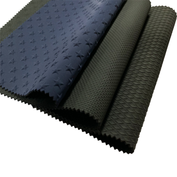
Converted foam parts can support die cutting, CNC cutting, lamination, adhesive backing, shaping, and layered insert structures.
Review Converting OptionsWhen die cutting is the better route
Die cutting makes sense when the insert uses simple repeated outlines. Tool silhouettes, straight pockets, sheet liners, foam pads, separators, and shallow accessory slots often fit this process well.
In addition, die cutting can be practical when the design is already confirmed. If the layout is unlikely to change, a die can support efficient repeat work and consistent part shape.
When CNC cutting is the better route
CNC cutting is stronger when the insert needs detailed pocket depth, curved walls, relief zones, or fast sample revision. It can help with test equipment, instruments, machined parts, camera-like devices, and irregular housings.
Also, CNC cutting is useful before a final production route is locked. A sample can be adjusted, tested, and refined before a larger program moves forward.
Application Scenarios for Tool Cases and Equipment Packaging
Different cases need different insert structures. A practical design should reflect the working environment, packing sequence, product sensitivity, and expected reuse level.
In addition, the insert should help the product set look complete and easy to inspect. This matters in field service, production packing, repair programs, equipment demonstrations, and sample kit management.
Field service tool kits
These cases need fast access, visible tool positions, and reliable return slots. EVA with contrast layering can help show missing items after service work.
Testing and measuring equipment
These inserts should protect displays, dials, ports, and sensors. Cavities should support strong body areas while leaving delicate details free from pressure.
Electronics and control units
A main unit, cable set, adapter, and accessory pack should not move together in one open space. Separate pockets reduce scratches and cable strain.
Sample and demonstration cases
A clean foam layout improves presentation and inspection. Color contrast can also make missing parts easier to notice before the case closes.
Industrial spare part kits
Small parts, machined components, and metal accessories need separation. Dedicated pockets help reduce surface marks and packing mistakes.
Reusable transport cases
Reusable cases need stronger cavity walls, practical removal space, and a structure that holds shape after repeated opening, closing, and repacking.
Sample Fitting, Adjustment, and Bulk Production Checklist
A foam insert sample should be checked with the real product and the real case. A drawing can confirm layout direction, but the sample confirms fit, access, lid pressure, edge quality, and movement control.
During sample review, the product should drop into place without forced pressure. It should also lift out without scraping, twisting, or catching on a fragile detail. Then the case should close smoothly without excessive pressure from the lid.
After that, the case should move through realistic handling positions. Flat movement, upright carrying, side tilt, and repeated opening can reveal fit issues that a static check may miss.
Fit check
Check whether the product sits flat, aligns with the cavity, and avoids pressure on fragile zones.
Removal check
Confirm that finger notches, lift gaps, and cavity depth allow practical removal without surface scraping.
Movement check
Move the closed case in realistic directions and check for rattling, sliding, or accessory contact.
Production check
Confirm material, thickness, color, layer stack, cutting method, tolerance, packaging, and approved reference sample.
Common adjustment notes
Good revision notes should be specific. “Too tight” is less useful than “increase clearance near the left connector by 1 mm.” Photos with arrows can also show where a notch should move or where a cavity should become deeper.
In addition, revision feedback should separate required changes from visual preferences. This keeps sample adjustment focused and reduces unnecessary rounds before production approval.
Specification and Inquiry Information Checklist
A clear inquiry file helps the insert project move faster. It reduces guessing before sample work and makes material direction, cutting method, and quotation review more accurate.
The following details are useful for drawing review and early sample planning:
- Product length, width, height, and approximate weight.
- Case inner size, lid clearance, corner radius, and any internal ribs or posts.
- Product drawing, DXF file, CAD file, PDF outline, sketch, or clear photos.
- Fragile zones such as screens, ports, lenses, polished surfaces, switches, and clips.
- Accessory list, cable positions, adapter size, manuals, spare parts, and packing sequence.
- Preferred material direction, such as EVA, PE, layered foam, or open recommendation.
- Color preference, contrast layer needs, surface appearance, and missing-part visibility goals.
- Expected sample quantity, pilot quantity, and repeat production quantity.
- Special concerns, such as vibration, repeated handling, storage pressure, dust, odor, or adhesive backing.
Finally, one practical note should be included: the main job of the insert. For example, the project may require fast tool access, stronger equipment cushioning, visual presentation, accessory control, or a balanced mix of all four.
Procurement and Design Advice Before Sampling
Before a foam insert moves into sampling, several practical questions should be answered. These questions help avoid overbuilding the insert, choosing the wrong material, or designing a cavity that looks neat but performs poorly.
First, define whether the case is mainly for transport, storage, demonstration, field service, or repeated internal handling. Each use changes the importance of cushioning, appearance, removal comfort, and durability.
Second, decide whether the insert should prioritize equipment protection or tool organization. Protection-focused inserts often need thicker support, more clearance planning, and lid foam review. Organization-focused inserts often need clean cavities, contrast colors, and easy access.
Finally, keep production rhythm in mind. A prototype case can use CNC cutting for fast adjustment. A stable repeat project may later use die cutting or layered die-cut construction if the geometry allows it.
A sample review should confirm fit, removal, lid pressure, accessory separation, and repeatable placement before bulk production.
View Foam ConvertingExtended Reading
The following YIBAO pages support material review, converting direction, and sample planning for tool case and equipment packaging projects.
Foam Converting
Review cutting, layering, lamination, adhesive backing, and shaped foam part options for tool case and equipment packaging projects.
View ConvertingEVA Business Department
Explore EVA foam directions for firm cavity layouts, layered inserts, tool case organization, and presentation-focused foam structures.
Explore EVA FoamPE Foam
Review PE foam options for cushioning, equipment blocking, case lining, and practical industrial packaging support.
View PE FoamFAQ
Summary and Practical Next Steps
In summary, a strong insert should fit the case, protect the product, organize the set, support repeated handling, and match the production plan. For tool cases and equipment packaging, custom foam inserts should be planned through real product geometry, material selection, cutting method, sample fitting, and clear production approval.
- First, prepare product dimensions, product photos, case inner size, and target quantity.
- Next, decide whether the insert should focus on tool organization, equipment cushioning, visual presentation, or mixed use.
- Finally, send drawings, equipment dimensions, and case size for material review, cutting method selection, and sample planning.
Send Drawings, Equipment Dimensions, and Case Size for Insert Review
A foam insert project becomes easier to review when the inquiry includes drawings, photos, case inner size, equipment weight, fragile zones, material preference, and expected quantity.
YIBAO can review the foam converting direction, material choice, cavity structure, sample plan, and production route based on the project information.